Showing posts with label CAD CASE STUDIES. Show all posts

Saturday, 15 November 2014

CAD PROJECT - CASE STUDY 7

PHOTOGRAPHIC SUBSTITUTION


CONCEPT :

Photographic Substitution is a technique in which a computer generated 3D model is superimposed  (kept on the top of) a realistic photograph to conduct a convincing and realistic presentation .  When we try this we get a better understating about whether the conceptual design properly  merges with the actual background in terms of proportion , colour , texture , etc. To create such a perfect presentation you have to perform the following activities .

1. Capture a photograph from the actual background using a digital camera.

2. Photo editing of the background image to remove unwanted objects using Adobe Photoshop .

3. Create the 3D Model of the object (to be superimposed on the background image) using AutoCAD .

4. Apply finishes (materials) , lights and camera (matching camera angle of the actual photograph) , using AutoCAD or 3DS Max

5. Render this model , save the image and overlay it on  the  background image using Adobe Photoshop . 


LIVE EXAMPLE :

A college has constructed a pavilion in connection with a basket ball court and they need to protect this place by providing a slopped roof with shingles . The college has provided the following photograph captured from the site .


As you can see , this background image needs some photo editing in the first place because there are some unwanted objects like pump set , support for painting etc. to be removed from the photograph .Then some additional details like flowers , pavement tiles etc are to be added on the image .This work is done in Photoshop . Click to enlarge this following image to see the image after photo editing .

After this photo editing work the 3D model of the protection for the pavilion is created using AutoCAD . A sloped roof is made and it is supported using frame work to protect the area below . Here is the image of the 3D Model . 


This file is taken to 3DStudio max  and a camera is placed which matches with the camera view of the background image . Perspective matching is done through trail and error method . (Preferably both these cameras should have the same parameters such as focal length , distance from the target etc. ) The rendered model without the background appears as shown below.


The following shingle tile was used to create the material


This image is taken to Adobe photoshop ,  pasted against the background image and the black transparent areas are deleted to get the realistic feel of the pavilion area protected by the framed roof . 


Such a presentation would be always be more effective and successful because seeing is believing.

Click on the following video to see the three stages :


Friday, 26 September 2014

CAD PROJECT - CASE STUDY 6


TRADITIONAL ARCHITECTURE CUSTOMISED 


 In this post I would like to share with you my experience with a traditional Architect . Such architects are only a few in my state and they have a tendency to use traditional elements in whatever designs they create (because they do lot of temple architecture)  . The skill to perform such an architecture is generally inherited from their ancestors  . Such a design will last over many years and will not undergo any change with time .

A few months back , I had a meeting with such an architect and his requirement was to make a 3D photo realistic view and an exterior animation for his project for a client who is a Doctor . When you go through plan , elevation and section of this project you can feel the complexity of the design . 


 It is basically a three storied house with some specialities . It has traditional elements incorporated which will be little bit time consuming to model using AutoCAD . This house has level difference inside , massive drawing area , central court yard , swimming pool on the first floor , vast open space and landscaping done on the second floor . Creating a 3D model of this house was a challenging job since the first presentation has to be done on the very next day ! . We have started the work in the morning , thinking that we will be able to  finish it at the most by the evening . But in between the architect was trying various possibilities to refine the design and as the 3D model became heavy it took more time to get the results after each zooms, pans and orbits etc.   We could finish it only by late night . You can see the views of the finished rough model below :


The architect was  not that happy with this design , because it looked too plain without  much traditional features which he was actually intending to incorporate .  But this was just a material for him to conduct that days presentation which was unavoidable . After the presentation the client has just got an idea but he was also demanding to modify the design . Next day I had a sitting with the architect and we have introduced some prominent traditional features into the design and it got a new interesting look .


The client liked this better than the previous design because of the presence of traditional features but he has suggested for some minor modifications . Detailing the gable end of the roofs , removing the pergola like members from the first floor roof slab , providing a hipped roof with gables for the ground floor was among the changes he has suggested .I have further incorporated those changes to fine tune the design . These are  the views given to the client in the final presentation . 


Since the client was also in need an exterior animation , I had to prepare animation along with each design which was a time consuming job .  The computer has worked for several hours to perform rendering  . Rendering - is the process of preparing each frame of an animation after applying the realistic materials , lights , camera etc. For 1  second animation 25 such frames are to be prepared by the computer .  When it comes to larger animations giving it to rendering farms is preferred to perform fast rendering  . Click on the link provided to see the exterior animation . I have prepared few segmental animations in 3Dstudio Max after importing the AutoCAD 3D model . Editing and sound effects are given using Adobe premier software .  This movie  clearly shows the level of detailing provided on elements like  windows , roof gables , brackets etc.

(Please expand the youtube window to the full screen watch the video in HD - 720P format)
Click here to see more such animations


Hence the project has to pass through three stages to get it finalised . When you work with such architects you will get more exposure in architectural design & visualisation  and learn lot of patience :)


Thursday, 7 August 2014

CAD PROJECT - CASE STUDY 5


VICTORIAN ARCHITECTURE

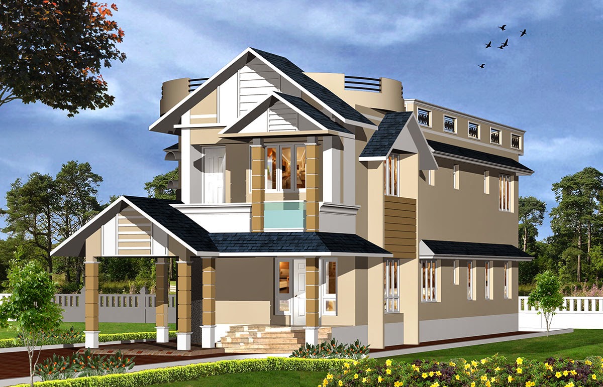
About a few months back one of my student who is a Civil engineer approached me and asked me to make a suitable elevation for the following plan for his client  .  (Please click to enlarge it) . To get a symmetrical elevation  he told me that the ground floor and the first floor should be typical.


The client has particularly insisted that the elevation should be simple and easy to execute . Since they preferred flat features I have provided the following elevation and one more colour choice .


After evaluating these elevations the clients personal choice was the second one with the white and blue combination .  That day the elevation was almost finalised and client was also happy with what he was given.
Next day the client happen to see a magazine which deals with building design and came across with an elevation there . He got impressed with that and he approached me demanding me to change his elevation (the one which was finalised ) to match with the one he has seen in the magazine  . Even if it was practically very difficult I was forced to make such an elevation to satisfy the client . I took whatever features possible from the elevation shown in the magazine and incorporated it in the client's plan .  The 3D view of that elevation is  shown below .


After making this elevation even I liked this view and the client got the best .......Whatever happened happened for good .... !


Friday, 20 June 2014

CAD PROJECT - CASE STUDY 4

A DREAM FULFILLED WITHIN THE SPACE CONSTRAINTS

There is gentleman out there in Canada with Indian origin who had a long cherished dream to make a house just as any other human . With this dream he searched for an elevation everywhere and finally located  an impressive one from the internet . That elevation is shown below :


He was so particular that  his plan should match perfectly with this elevation .   But the site condition was in such a way that it was a lengthy plot with a width (frontage)  of hardly 10 meters . After leaving the setbacks the the frontage of the house will have a width of 6.7 meters . Please see the plan :

So its practically impossible to design an identical elevation for this plan since the elevation which was given to me had three wider spans .  Hence the job became challenging . After several contemplations  we have decided to cut down the width , eliminated one span  and created an elevation using Adobe Photoshop after photo editing the given elevation . (we have used Photoshop for this because making drastic changes in a photograph was relatively easier than making it in a 3D model ) .    This elevation was suitable for the client's plan .


Based on this elevation we have created 3D views by performing modelling using AutoCAD , Rendering using 3DstudioMAX and Photo editing using Adobe Photoshop :  The AutoCAD 3D model is shown below 


The finished views of the project from various angles :


Now the client has accepted this design and he is happy :) 

Hence the clients dream is fulfilled even if there was space constraints .  Because these software tools has helped us to provide the most ideal design solution for this client .


Your feedbacks and clarifications on this expected ....


CAD PROJECT - CASE STUDY 3

LOCATING THE RIGHT ROOFING SOLUTION

In Kerala (India) climatic conditions ,  flat roof is not preferred because of  the alternating weather  patterns of summer and heavy rain . So most of the houses with flat roof will be given a protection of trussed sloped roof and the design of this roof becomes challenging when the wall layout is relatively complex . The following photo shows such a house with flat roof and the client was planing to provide a sloped roof . But he was trying to determine the slope and layout this roof using manual methods . He has collected several opinions but was not in a position to take a right decision   


When this client has approached me I have decided to make a model of  the roof of this house using AutoCAD . In Autocad using DVIEW command we can precisely find out the amount to roof exposed when we take a view from the eye level  , So that we can reach on to the correct angle of the roof to get optimum visibility (refer the video given below to know more about the DVIEW command ) . On the other hand if we give a fixed angle (say 30 degree) the rise of the roof may be too high because of the huge wall span . After the roof design I have rendered it in 3DSMAX and superimposed that image with actual photograph of the house in adobe photoshop . I have tried two different roof patters and the second pattern is finalised .


The superimposed view is given below :


You can use the following videos for further reference (from my youtube CAD training channel www.youtube.com/sabeercad)

Learn more about Dview command :


The procedure to make a Sloped roof :


The procedure to make a Gable end for the sloped roof :


Your feedbacks related with this post expected ....


CAD PROJECT - CASE STUDY 2

FROM PAPER TO COMPUTER - ADD A TOUCH OF REALISM

This pencil drawing of a villa project is designed and drawn by one the famous architects . The architect is so much talented that he can sketch any architectural / landscape / figure in few minutes how ever complex it be .I admire his talents ....

   After making this drawing it was given to me to visualise in 3D after incorporating all the finishes , textures , lighting , environment etc. and this was used to market and sell the villa project . You can see the touch of realism once it get converted to a photo realistic view . Thats the power of CAD !

Your comments on this expected ...


Thursday, 19 June 2014

CAD PROJECT - CASE STUDY -1

In this case study I would like to post a renovation project  . 

The older version of the house looks as you see below (its present form)


This house is about 25 years old and the client want to  make it a modern looking one with some touch of colonial architecture . We took the measurement from the actual site and made the model of this house using AutoCAD 3d , rendered it using 3DstudioMAX and edited the rendered image using adobe photoshop to get a photo-realistic image . Now the client is in the process of demolishing and reconstructing this house with little effort with the view provided . Along the with view the actual measurements required to execute the project (taken from the Autocad 3d model) is also given


The same view is given with a different color scheme which as more lively